Double-Layer Circuit Board

Double-Layer Circuit Board

What is a Double-Layer Circuit Board?

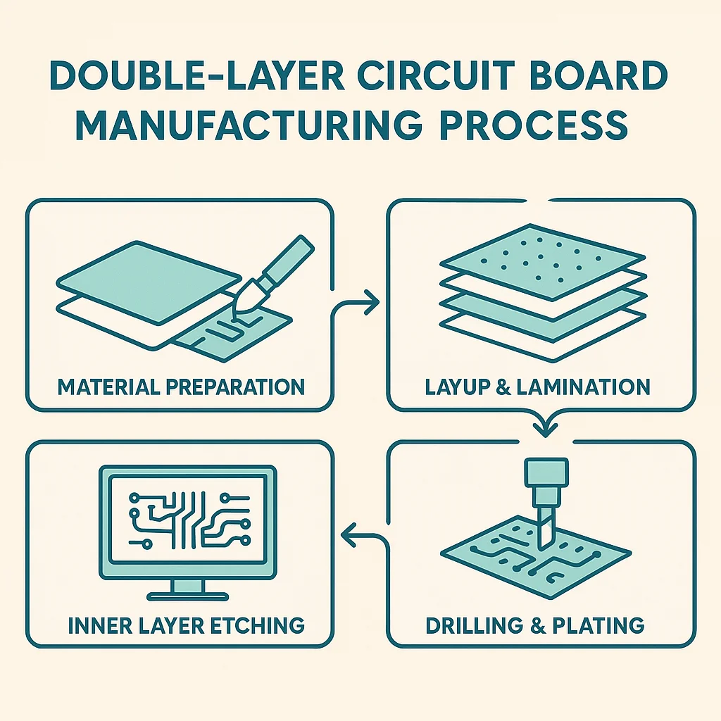
A Double-Layer Circuit Board, often referred to as a double-sided PCB, is a printed circuit board that includes conductive copper layers on both its top and bottom sides. This dual-layer configuration allows for more intricate circuit designs and greater routing capabilities compared to traditional single-layer boards.

While single-layer PCBs have limited space and are suitable for simple applications, double-layer PCBs provide expanded room for component placement and signal pathways. This makes them a preferred choice for today’s compact yet powerful electronic devices.

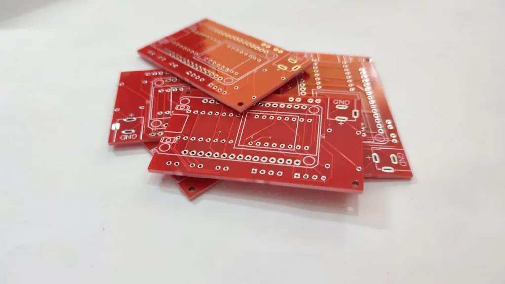
At  Ittefaq Electrotech, we manufacture premium-quality double-layer circuit boards engineered for precision, durability, and performance. Our advanced production techniques ensure that each board meets the high standards required for complex and high-functioning electronic systems.

Supports more complex and compact designs.

A Double-Layer Circuit Board is ideal for moderately complex electronic devices like power supplies, industrial controls, automotive electronics, and more. The best part is that it is more affordable than multilayer boards while being more capable than single-layer boards.

  • Smartphones, tablets, televisions, remote controls, and smartwatches.
  • Control panels, sensors, monitoring devices, motor controllers, and automation systems.
  • Car dashboards, infotainment systems, LED lighting, power modules, and engine control units.
  • Diagnostic tools, monitoring equipment, portable medical devices, and imaging system
  • AC-DC converters, DC-DC regulators, and uninterruptible power supplies (UPS).
1

High-Quality Copper Material

High-quality copper is used in double-layer PCBs to ensure smooth signal flow and low resistance. Its thickness is adjusted to meet the power needs of different electronic devices.

2

Advanced Substrate Materials

Double-layer PCBs use sturdy materials like FR4, providing strength, heat resistance, and insulation—ideal for tough environments and high-performance use.

3

Superior Signal Integrity

Double-layer PCBs offer strong signal integrity by reducing loss and interference, making them perfect for high-speed, data-sensitive devices like telecom systems, computers, and medical electronics.

4

Enhanced Heat Dissipation

Double-layer PCBs use heat-conductive materials like copper to spread heat evenly, reducing the risk of overheating and improving the durability of components in high-performance devices.

Why Ittefaq Electrotech is the Best Choice for PCB Services

Why Us for Double-Layer Circuit Board Production

High-Quality Manufacturing

We use advanced technology and equipment to precisely manufacture double-layer PCBs, ensuring top quality and compliance with the highest industry standards.

Quality Assurance

Each PCB undergoes thorough quality checks, including electrical testing and visual inspections, to guarantee reliability and functionality.

Timely Production

We prioritize on-time production, ensuring your double-layer PCBs are delivered as scheduled without compromising on quality.

Competitive Pricing

Our efficient production process helps minimize costs, providing high-quality PCBs at competitive prices, without sacrificing performance.

Double-Layer Circuit Board Production

The Double-Layer Circuit Board Process involves the following key steps to create a functional and reliable PCB:

Substrate Preparation

The substrate preparation process begins with selecting a suitable base material, which is essential for double-layer circuit board manufacturing. Typically, FR4 (fiberglass epoxy) is used. Copper is laminated on both sides of the substrate, forming the foundation for the circuitry on each layer.

Image Transfer

During the image transfer step, a light-sensitive film called photoresist is applied to both sides of the copper-clad board. The board is then exposed to UV light through a transparent mask containing the circuit design. The UV light hardens the exposed areas of the photoresist, while the unexposed areas remain soft. These soft areas are subsequently washed away, revealing the circuit paths that will be etched.

Etching

An etching solution—commonly ferric chloride or ammonium persulfate—is used to remove the unexposed, softer photoresist along with the underlying copper. This process leaves only the desired copper traces that define the circuit paths on both sides of the board.

Drilling

Accurate holes, known as vias, are drilled at specific locations to establish electrical connections between the top and bottom copper layers, ensuring proper interlayer conductivity.

Plating Through-Holes (PTH)

Copper is electroplated into the drilled holes to create conductive pathways between layers. This essential process allows electrical signals to travel from one side of the PCB to the other.

Solder Mask and Silkscreen

A solder mask is applied over the copper traces to prevent oxidation and reduce the risk of solder bridges during assembly. Following this, a silkscreen layer is printed to display labels, component markings, and logos for easier identification.

Surface Finish

To improve solderability and shield exposed copper pads from corrosion, a surface finish is applied—commonly HASL (Hot Air Solder Leveling), ENIG (Electroless Nickel Immersion Gold), or OSP (Organic Solderability Preservative).

Electrical Testing and Quality Control

Finally, the PCB undergoes electrical testing to verify continuity and detect any shorts. Visual and automated inspections are performed to ensure the board complies with design specifications and quality standards.

Get in Touch

Contact Us Today

If you have any questions about PCB manufacturing or would like to learn more about our fabrication services, feel free to contact our team. Our experts are ready to assist you with tailored solutions and guide you through every stage of your PCB project.

Scroll to Top